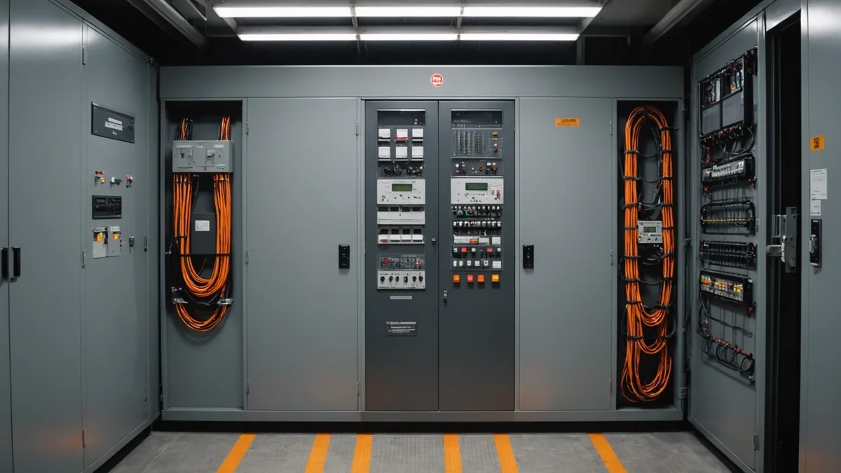
The pre-submission internal review is where most permit correction items should be caught. In practice, many are not. This is not a technical knowledge gap. The engineers who receive correction notices can almost always identify immediately what the plan checker wanted and acknowledge they could have provided it before submission. The gap is procedural: internal review happens under time pressure, follows no written checklist, and relies on the reviewer's memory of what plan check historically flags.
This post lays out a review structure that matches how a plan checker actually evaluates a commercial electrical drawing set. It is not a complete QC protocol for the engineering design itself. It focuses on the items that generate permit correction comments, which are not always the same things a PE reviewing for design quality would catch.
Cover Sheet and Drawing Index
Start with the cover sheet. Verify the project address and jurisdiction match the permit application. Confirm the adopted code edition and local amendments are listed. If the jurisdiction requires specific notes (utility name, available fault current source, building occupancy classification), those should be on the cover sheet or the drawing that the cover sheet references.
The drawing index must list every sheet in the set. A plan checker who does not see a required drawing type listed in the index will call it missing, even if the information is buried in another sheet. Required drawing types for commercial electrical typically include the electrical site plan, single-line diagram, panel schedules, load calculation, riser diagram, and any required arc flash or fault current study. Labeling conventions should be consistent: if your panel schedule sheets are labeled E-5.1 through E-5.4 in the index, they should carry those same labels on the title block of each sheet.
Single-Line Diagram
The single-line diagram is the highest-scrutiny sheet in most commercial electrical submissions. Check the following items in order:
First, verify that available fault current at the utility service entrance is shown, with a note identifying the source of that value (utility coordination letter, utility published data, or short-circuit study). Most AHJs require this for any service above 400A and many require it for smaller services as well.
Second, confirm that all overcurrent devices show both their ampere rating and their interrupting capacity. The interrupting capacity must be at least equal to the available fault current at that point in the system. If a 100A circuit breaker with a 10 kAIC interrupting rating sits at a panel where the available short-circuit current is 18 kA, that is a code violation under NEC Article 110.9 and it will be flagged.
Third, check that service disconnect rating, service entrance conductor size, and load calculation service total are consistent. A 2000A service disconnect with a load calculation showing only 800A of connected demand may generate a question from the plan checker about whether the service is oversized or whether the load calculation is incomplete.
Fourth, confirm that all feeders shown on the single-line match the conductors shown on the riser diagram. Panel designations should be identical on both sheets.
Panel Schedules
Panel schedules are frequently produced from separate drafting tools or templates and then assembled into the drawing set. Cross-contamination between projects and copy-paste errors are common. Before submission, verify that every panel schedule shows the correct panel designation, bus ampacity, main breaker rating, and voltage configuration for this specific project.
Check that the connected load total on each panel schedule is consistent with the load appearing for that panel in the load calculation. Also verify that the panel schedule shows the neutral and ground conductor sizing. Some plan checkers specifically look for neutral conductor sizing under NEC Section 220.61 for services and feeders with significant nonlinear loads.
For panels with electronic or variable frequency drive loads, check whether the panel schedule notes that the neutral conductor is sized for harmonic currents. This is not universally required, but in jurisdictions that are strict about NEC Section 310.15(A)(2) on ampacity derating for harmonic-producing loads, missing this can generate a comment.
Load Calculation
The load calculation sheet is checked by the plan reviewer against the panel schedules and the service size. Verify that the calculation addresses all load types present on the project: lighting, receptacles, HVAC equipment, motors, special loads, and any EV charging circuits required or anticipated. Demand factors must be applied correctly per NEC Article 220, and the calculation must identify whether the standard method or the optional calculation method under Part V of Article 220 is being used.
The most common load calculation error that generates a plan check comment is an incomplete account of HVAC loads. If the electrical drawings show a mechanical equipment schedule or reference mechanical drawings, the plan checker will expect the electrical load calculation to account for the motor loads shown. Discrepancies between the mechanical equipment schedule horsepower ratings and the electrical load calculation inputs are a consistent source of correction items.
Riser Diagram
The riser diagram should show all feeders and their routing from the service equipment to each distribution panel and major load. Conductor sizes, conduit types, and panel designations must match the single-line diagram and the panel schedules. Any discrepancy between the three sheets will generate a comment asking which drawing governs.
Floor-by-floor panel locations should be shown with consistent panel designations. If Panel LP-3 appears on the single-line, it should appear with the same designation and on the same floor in the riser diagram. Riser diagrams that label panels differently from the single-line are among the most common sources of correction comments on complex multi-floor projects.
A Note on What Pre-Submission Review Cannot Catch
This checklist targets the permit-readiness items that generate plan check corrections. It does not replace a PE's engineering review of the design itself. Load calculations can pass a permit QC check and still contain design errors; a panel schedule can be consistently labeled and still have a circuit configuration that violates the NEC.
We are not saying that permit QC and engineering review are the same thing. They are separate activities with different goals, and a drawing set needs both before it goes to the permit office. The order matters: engineering review should happen first, and permit QC should follow as the final step before submission. Running them in parallel or conflating them is the process failure that puts drawings in front of plan checkers with avoidable deficiencies still in them.